|
Well since my current main project is a bit of a drag, and my cheap chinese lidar scanner arrived, I thought I tackle this project...to distance from my big project for a few days. It became a repeating element to cover new grounds at christmas times anyway, and this year was also in that tradition.
And since the lidar arrived, I thought this would be a quick hit and run project I had in my mind since I saw those cheap scanners the first time.
You know: low investment > high reward.
Mechanics
Most parts are 3d printed, the table with the gear sits on a cheap bought aluminium L-bracket wich can be connected to a regular arca swiss plate.
The motor is attached via a 3d printed L shape. All elements have slotted holes for easier adjustment / assembly.
Might need to revisit it, since I'm not 100% satisfied with the construction. Printing time was surprisingly fast: only one day needed, for construction and print.
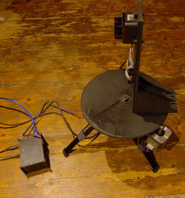
The hardware setup.. the 3d printed box contains the Arduino + Shield
Electronics
The motor is controlled via an Arduino and a CNC shield. Those are very affordeable. (around 15 bucks). The chipsets overheats due to the high amps needed for the motor in continious mode, But for the small steps and pauses during scan this works just fine.
Those parts, CNC shield and motor I had for another project, wich I doubt I'll will ever start due to the results of this project..(sound level) To get the cnc shield working I had some problems with unstable power supply, wich resulted in some unexpected and incomprehensible results, wich did cost me also a few hours.
The lidar scanner LD19 is designed for robotic navigation, this was the most costy part of the whole build (120 bucks). its a rotating infrared laser wich continiously send out data via usb.
Yes its loud: Initial motor test
Programming
When I started this project, I had no clue on serial port communication in C++. So a lot of research went into it. Controlling the CNC shield was more or less a no brainer. The LD19 on the other hand was harder, since it is a pretty "stupid" device:
You plug it in and it sends out data packages continiuosly. The example wich comes with the laser is written in a linux specific code, and interfaces with ros/ros2 (Robot operating system). A lot of time went into it figuring out how to replicate this in a windows environment...wich was failure after failure. Luckily I found a boost port of it wich I could adapted.
Afterwards it might be just a problem of using the wrong bitrate for serial communication wich tripped me of.
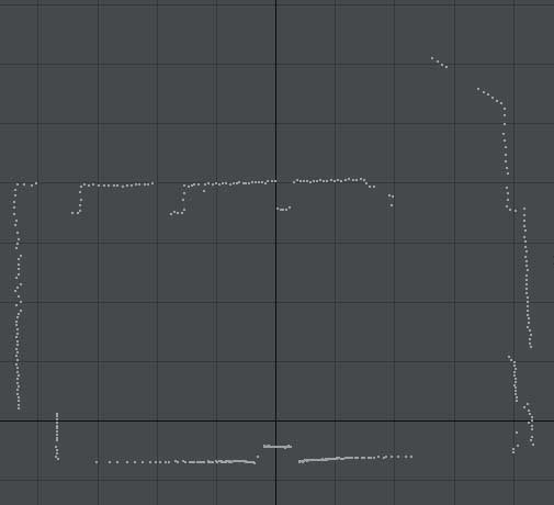
The promising first result of one data package.
Basically the code fetches 10 data packets from the lidar. For each point in each packet (Around 500 points, it calculates the XY coordinates from the angle/range data (Basic SIN/COS) then it rotates the point around Z (also basic SIN/COS) by an specifified angle , wich is a basic counter. Then it continiously writes those vertex position values to a simple .obj textfile. After that it rotates the plate by a simple G01 command, and adds a value to the Z angle. and starts again.
My problem was that I was lazy, and didn't exported the raw input from the beginning, wich resulted in some time intensive rescans. This and two pesky bugs in the code, took me way longer than it neded to be (loosing around 5 hours). Also those bugs had an impact on the result way into the scan, so I needed around 15 minutes to rescan unti it showed up... I know stupid me.
Starts correcly and then warps. Took me way longer than expected
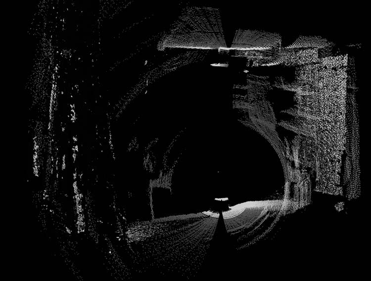
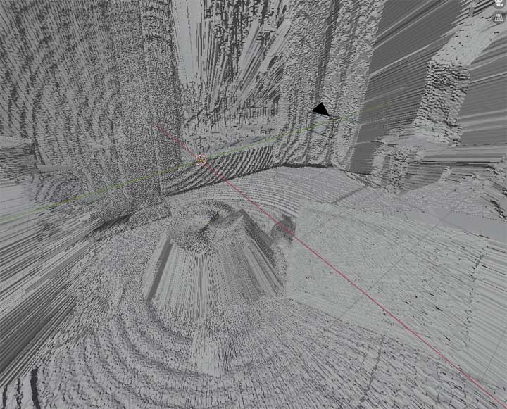
The pointcloud is then feeded into meshlab and a mesh is generated via the Surface Reconstruction - Ball Pivoting filter.
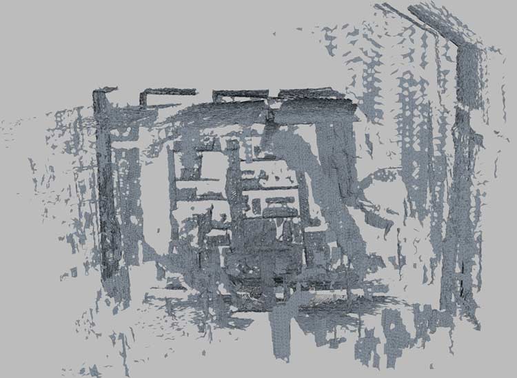
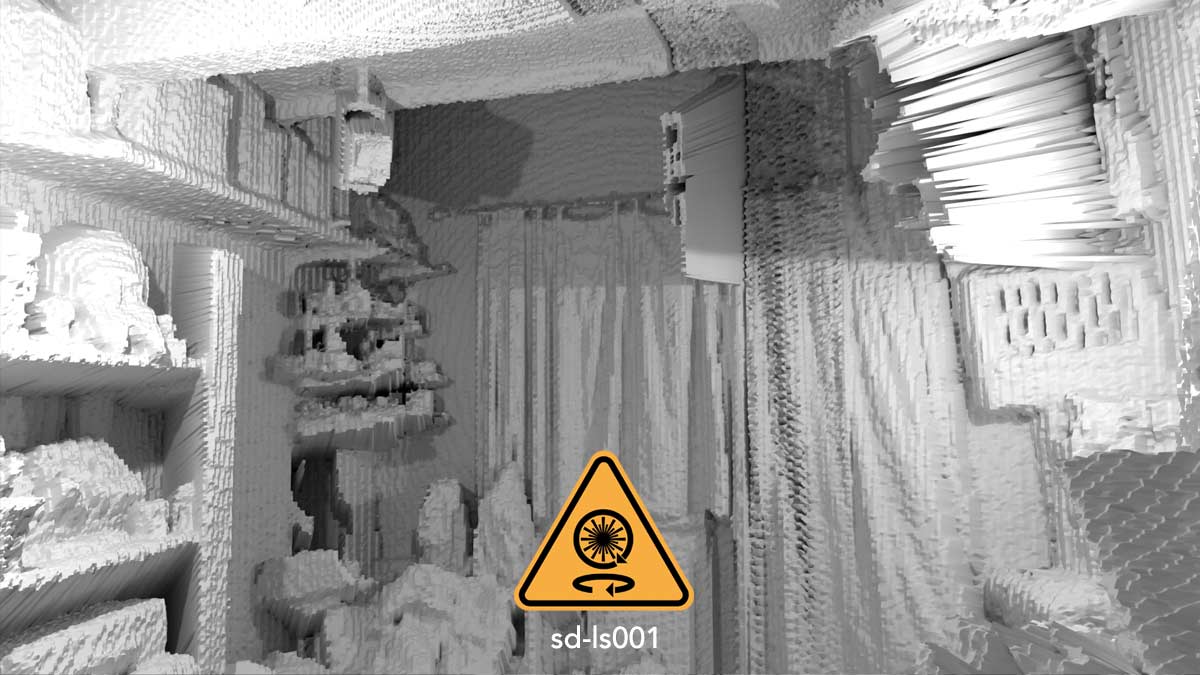
The scanned room...notice the missing walls...defintive one thing to investigate further.
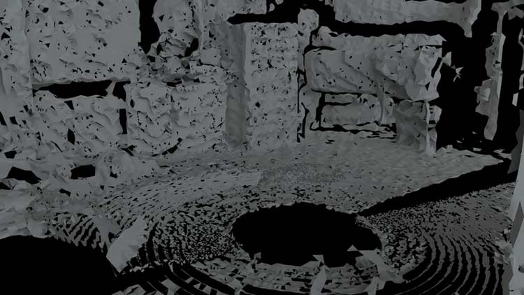
some render of the detail level to currently expect.
Post mortem...so far
The lidar does well on cloth wood and tinted glass. It does not like the walls of the room (rough texture). It takes around 30 minutes for a complete scan. Wich for certain use case is too much.
I might add additional data packets to increase the resolution. The next thing to do is to capture a room and additionally photograph a 360 HDRI environment at the same position. Just to see how well they correlate to each other.
After this I will generate my first 360 depth map out of it.And last but not least, compare it with a traditional photogrammetry method done in the same amount of time. And last but not least, there is room for improvement, like using more data packages, and try to use the reliability value of the lidar device. In short how well the output is if you process the raw data.
Sure its not a Faro / Leica.... but whats the point. I doubt I will ever get the hands on one of those 45k bucks and more machines, nor will I have the need to use one of those. In fact this low level approach will be imho a better vehicle for learning the in and outs of 3d environment scanning, more than a machine wich does everything with the press of a button. (metaphorical speaking, I have no idea how those operate). So doing it the hard and unreliable way works actually in my favor education wise.
One thing for sure, this will get another post mortem.
Overall this was a nice 4 day project, wich covered a lot in areas I wanted to progress anyway.
POST MORTEM 2
Still need to do some fine adjustments, this is a view of the mesh, with an captured 360 hdri projected onto it.
Next to do is to increase the amount of captured points and play a bit with the meshing options in meshlab
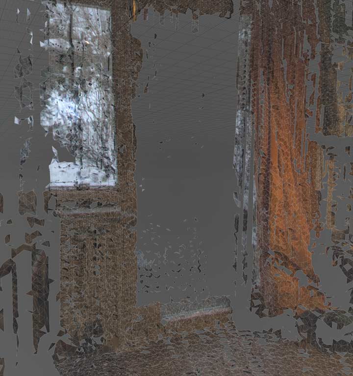 Still too much holes. but I'm surprised how well the projection fits with the mesh Still too much holes. but I'm surprised how well the projection fits with the mesh
POST MORTEM 3
Changed the CNC stepper motor controller to use substepping wich results in a much smoother motion. The data uses now more data packages, wich unfortunately does not result in better results in meshlab. I fear I have to implment my own meshing algorythm. As a first step I made an interpolated depth image map
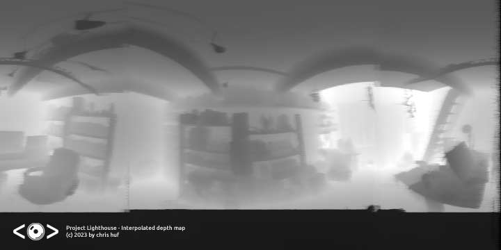
still a bit rough (no interpolation wrapping, but promising results
Post Mortem 4
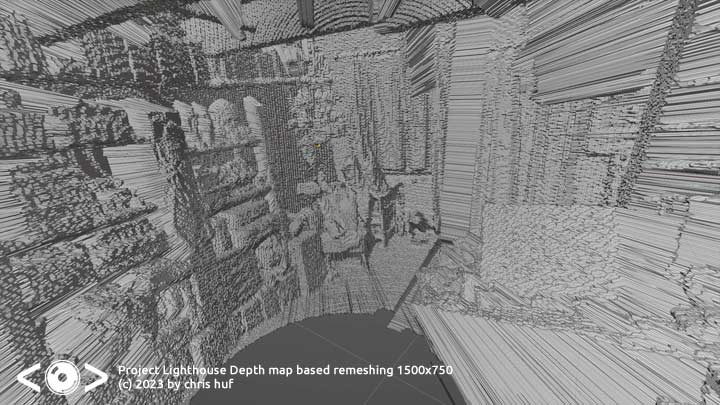
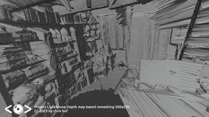
The advantage of doing a depth map based remeshing is, that you reduce a 3d problem to a 2D one, In fact by doing so, you get a nice little error correction without any complex algorithms: Multiple points at close locations, with varing depth merge to a simple coordinate. Also by doing so you can make the object waterthight. And the generation is fast.
A lower resolution bitmaph result in lesser detail but with more accurate positions and a smoother surface.
Some further calibration has been done also. Now its time to capture another environment, and check if I can eliminate the strange "shift" the laser has between points in one 180 degree field and the other
Post Mortem 4.5
Run again a scan with 20 data packets per slice. This time with an overlap Found a fix to the vertical angle alignment problem and "calibrated" the heading data. Then I took a 360 hdri at more or less the same location, and aligned/mapped it via a null object on the mesh.
Results are still not 100% to my satisfaction, but Im still surprised what you can get out of this cheap scanner (scanning time 30 minutes).
Mapping test
Overall material costs of the project:
CNC Shield
Lidar Module
L Bracket
Motor
Screws
Bearings
Cable USB 2 Printer
Cable USB2 Lidar
Filament
Glue
Sum |
13.00
114.00
11.00
26.00 (sold in a package of 3)
10.00 (various screws set)
5.00 (sold in a package of 10)
2.00
5.00
6.00 (around a third of a spool)
7.00
____________
198.00 |
As said everything except the lidar scanner was already in posession, making the project costs even cheaper.
I'm pretty sure there already is a program, but if there is interest I split out the depth map generation (without the scanning functionality) to an external program.
So where to continue from here:
Hardware side: Try to get it working with a power bank.
Software side: Combine multiple scans....currently I have no idea how to auto align them, and looking back on aligning the hdr with the mesh, it could be a nightmare.
As for mixing multiple scans: I would actually go very simple with raycast and polygon size. If they ray from scan 2 hits a polygon wich is in size above a certain threshhold (longest edge) in scan 1, and the polygon size of the scan 2 is smaller, use this instead: By doing it that way you just eliminate the stretched (= occluded) parts of the first scan. But this is way in the future, and other projects have to be finished first before I get into that,
Post Mortem 5 (last)
Not much done this weekend, (Regenerating) so I did the brainless stuff: My existing powerbank is strong enough to support the motor, so outdoor scans are possible (yeah), Unfortunately the usb cable is not en par in quality, and I need a better / longer one to get the lidar recognised on the laptop (used a smaller one for testing). here is a video of the scanner in action. I guess I can make 4-5 scans with one charge of the powerbank.
Mobility test
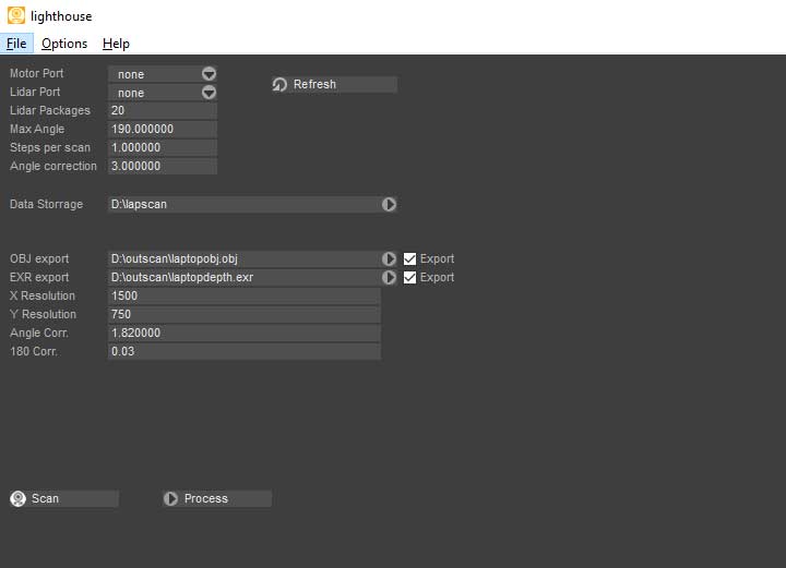
Also I did the tedious braindead stuff and put all hardcoded values into the interface. Looks ugly, but I think I can do make it a bit fancy during weekdays.
Scan result
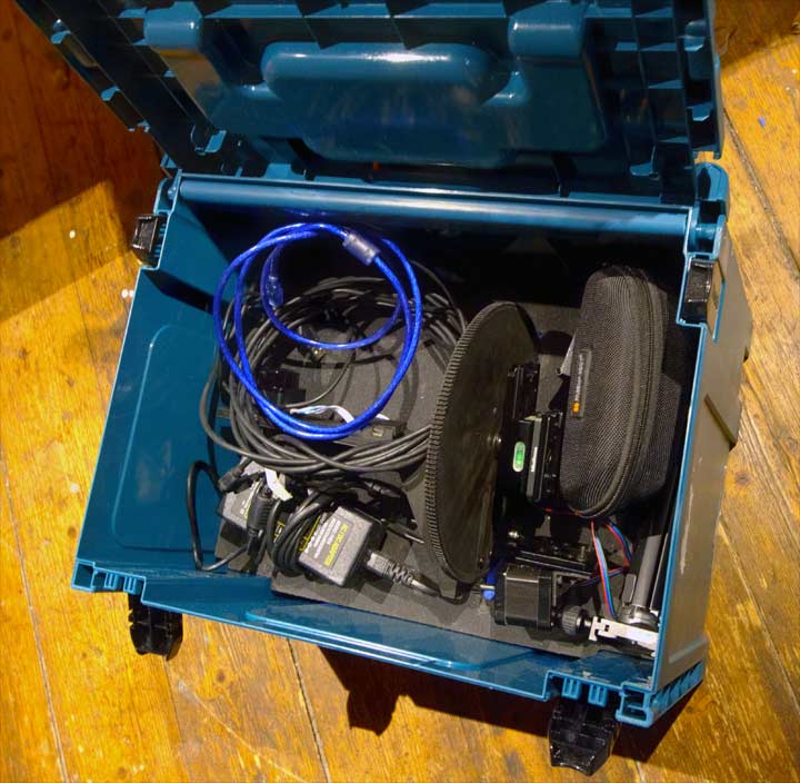
Packed away until weather/vegetation is good enough for an outdoor trip
This is the last post mortem. Outdoor Results and further development will go into a new article. I think I'll release
the software for free once I polished things up, because the project is more or less done.
If you got question feel free to discuss it down below.

|